Books
Instrumentation
Click here to view the PDF for the above topic
Primary Sensing Mechanisms
|
Resistive Sensing Elements
a. Resistance Temperature Detector (RTD) The RTD incorporates pure metals or certain alloys that increase in resistance as temperature increases and, conversely, decrease in resistance as temperature decreases. RTD act somewhat like an electrical transducer, converting changes in temperature to voltage signals by the measurement of resistance. |
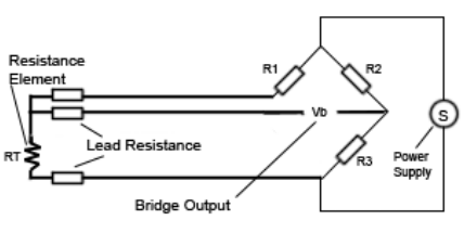
Circuit Diagram of RTD
|
The metals that are best suited for use as RTD sensors are pure, of uniform quality, stable within a given range of temperature, and able to give reproducible resistance-temperature readings. RTD elements are normally constructed of platinum, copper, or nickel. These metals are best suited for RTD applications because of their linear resistance-temperature characteristics.

The above equation represents the Resistance vs. Temperature relationship where R is the resistance and temperature T , with reference Resistance and coefficient of resistance as The coefficient of resistance is the change in resistance per degree change in temperature, usually expressed as a percentage per degree of temperature.
|
b. Bellows Resistance Transducer
Bellows Resistance Transducer is resistance type transducers which has moving contacts (slide wire variable resistors). The pressure change causes a resistance change due to the distortion of the wire. The value of the pressure can be found by measuring the change in resistance of the wire grid. The following equation shows the resistance relationship. |
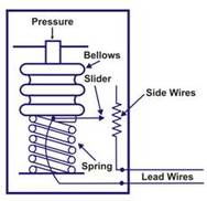
Schematic Diagram of Bellows Resistance Transducer
|

Where R is resistance of the wire grid (in ohms) K is resistivity constant for the particular type of wire grid, L is the length of wire grid and A is the cross sectional area of wire grid. As pressure changes, the bellows will either expand or contract. This expansion and contraction causes the attached slider to move along the slide wire, increasing or decreasing the resistance, and thereby indicating an increase or decrease in pressure.
|
Capacitive Sensing Elements
A common method of level measurement is to use a capacitance bridge. A typical arrangement is shown in Fig. in which the sensor consists of two concentric metal cylinders. In the case of a circular tank, the wall of the tank can be employed as the outer cylinder of the sensor. The capacitance of the sensor is: 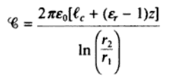
|
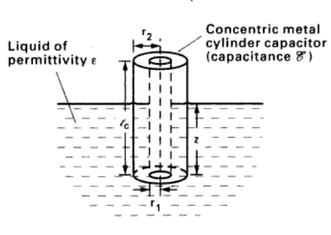
Concentric Cylinder Capacitor
|
where the cylinders are of height lc, and contain liquid up to depth z within the annulus. e0 is the permittivity of free space (8.85x10^(-12) farads/metre), er is the relative permittivity of the liquid involved, and r2 and r1 are the radii of the cylinders (r2 > r1)
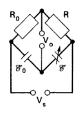
Capacitance Bridge
|
Capacitive sensing elements are incorporated into either electrical oscillator circuits or into a.c. deflection bridge circuits. An example or the latter is shown in Fig. In this the output voltage is:
|
Inductive Sensing Elements
|
Thermo-electric Sensing Elements
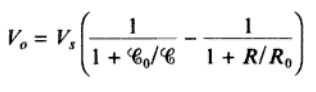
Thermocouple Thermocouples are the most popular temperature sensors. They are inexpensive, interchangeable, have standard connectors and can measure a wide range of temperatures. Their main limitation is accuracy as the system errors of less than 1°C can be difficult to achieve. Following figure represents internal construction of thermocouple and its circuitry. A thermocouple is constructed of two dissimilar metal wires joined at one end. |
Construction of Thermocouple
|
It works on the principle of “Seebeck effect” whereby electromagnetic force is generated when two dissimilar metals are joined at two different temperature ends. When one end of each wire is connected to a measuring instrument, the thermocouple becomes a sensitive and highly accurate measuring device. Heating the measuring junction of the thermocouple produces a voltage which is greater than the voltage across the reference junction. The difference between the two voltages is proportional to the difference in temperature and can be measured on the voltmeter (in mV). Thermocouples may be constructed of several different combinations of materials. The most important factor to be considered when selecting a pair of materials is the "thermoelectric difference" between the two materials. A significant difference between the two materials will result in better thermocouple performance.
Piezo-electric Sensing Elements
Elastic Sensing Elements
Pneumatic Sensing Element
|
Differential Pressure Sensing Elements
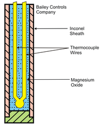
Differential Pressure Cell (DPC) The differential pressure cell (DPC) measures the difference between two or more pressures introduced as inputs to its sensing unit. The sensing unit consists of a diaphragm and a pressure cavity to create a variable capacitor which detects strain due to applied pressure. The following figure presents a schematic of the sensing unit of the DPC. The cell contains two compartments separated by a diaphragm. |
Schematic representation of DPC
|
The differential pressure acting on the diaphragm, due to pressures exerted on its two sides, results in displacement of the diaphragm. This displacement of diaphragm is transduced to electrical signal which is transmitted and recorded through appropriate instrumentation. The displacement of diaphragm is usually linearly calibrated to the differential pressure acting on it. The ends of the DPC are capillary tubes. Compartment is filled with some liquid ( e.g . silicone oil) of mass m. The ends are connected to processing units of which the differential pressure needs to be measured. Often the End 2 is left open to the atmosphere when the pressure at only one end needs to be measured. The following force balance will be in place:
Expansion Sensing Elements
Valves and Drives
|
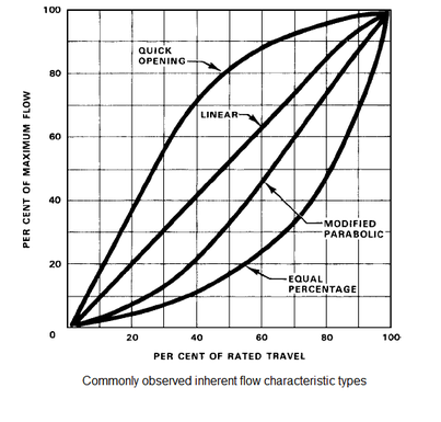
Valve Selection & Characterization:
1. Equal Percentage: equal increments of valve travel produce an equal percentage in flow change 2. Linear: valve travel is directly proportional to the valve stoke 3. Quick opening: large increase in flow with a small change in valve stroke Field of application for the above mentioned valves (Selection for Application): 1. Equal Percentage (most commonly used for valve control) - a. Used in processes where large changes in pressure drop are expected b. Used in processes where a small percentage of the total pressure drop is permitted by the valve c. Used in temperature and pressure control loops |
|
2. Linear -
a. Used in liquid level or flow loops
b. Used in systems where the pressure drop across the valve is expected to remain fairly constant (i.e. steady state systems)
3. Quick Opening -
a. Used for frequent on-off service
b. Used for processes where "instantly" large flow is needed (i.e. safety systems or cooling water systems)
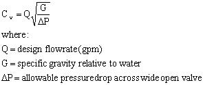
Valve Sizing
The steps involved in the sizing of a valve are as follows:
Step 1 – Define the System
Step 2 – Define a maximum allowable pressure drop for the valve
Step 3 – Calculate the valve characteristic
a. Used in liquid level or flow loops
b. Used in systems where the pressure drop across the valve is expected to remain fairly constant (i.e. steady state systems)
3. Quick Opening -
a. Used for frequent on-off service
b. Used for processes where "instantly" large flow is needed (i.e. safety systems or cooling water systems)
Valve Sizing
The steps involved in the sizing of a valve are as follows:
Step 1 – Define the System
Step 2 – Define a maximum allowable pressure drop for the valve
Step 3 – Calculate the valve characteristic
Step 4 – Preliminary valve selection
The Cv value value shoud be used as a guide for the valve selection
Step 5 – Check the Cv and stroke percentage at the minimum flow
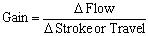
Step 6 – Check the gain across applicable flowrates
The Cv value value shoud be used as a guide for the valve selection
Step 5 – Check the Cv and stroke percentage at the minimum flow
Step 6 – Check the gain across applicable flowrates
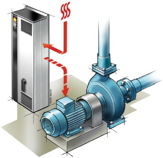
Variable Drives
A variable-frequency drive (VFD) is a type of adjustable-speed drive. It is used in electro-mechanical drive systems to control AC motor speed and torque by varying motor input frequency and voltage. Systems employed for motion control are called drives and may employ any of the prime movers such as diesel or petrol engines ,electric motors, for supplying mechanical energy for motion control. Drives employing electrical motors are known as electrical drives.
|
A variable frequency drive generally consists of following:
a. AC motor b. Main controller assembly c. Operator interface a. AC motor: It is usually a 3 – phase induction motor driven by an alternating current. The magnetic field on the rotor is either generated by current delivered through slip rings or by a permanent magnet. b. The main controller assembly: It is a solid state power electronic conversion device & consists of three main parts - i. Bridge rectifier ii. DC link iii. Inverter c. Operator interface : It often includes an alphanumeric display and/or indication lights and meters to provide information about the operation of the drive. A serial communications port is also often available to allow the VFD to be configured, adjusted, monitored and controlled using a computer |
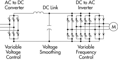
Circuit Diagram of VFD
|
Methods of Control: Out of all the methods, Pulse Width Modulation (PWM), is the one that is commonly used.
Types of VFDs
i. Voltage source inverter fed drives i.e. constant voltage
ii. Current source inverter fed drives i.e. constant current
Factors affecting Speed Control:
i. Cooling of the motor is usually not good in low speed range
ii. When frequency reaches zero, motor is shut off.
iii. The motor shall require a load reactor and filters if the pump leads from the VFD exceed certain conditions
Advantages:
i. Stable and reliable performance
ii. Saves energy and therefore reduces energy costs
iii. Isolated control signal provided by fibre optics between Power cell and Controller
Applications:
i. VFDs are frequently used to control motors for: Fans, Pumps, Compressors Mills.
ii. Oil & Gas, petroleum, petro-chemistry: oil transfer pumps, compressors, pumps, etc.
iii. Mining: mortar pumps, fans, etc.
iv. Water and waste water: water supply pump, etc.
Selection of DAQ Cards
Data acquisition systems come in three different types
1- Laboratory
2- Distributed
3 - Portable.
Laboratory and distributed systems are typically stationary, permanently placed systems composed of relatively large or bulky hardware and connect to desk-top computers in one way or another. These systems depend on the computer to access, process, and analyse input data and prepare it for presentation.
Portable systems, in contrast, are small, lightweight boxes that are easily hand carried and work with laptop computers or no computer at all when installed at a site to record data only.
The critical functional parameters that govern the selection of DAQ Cards are:
i. Accuracy
ii. Resolution
iii. Sampling rate.
I. Accuracy: It can be defined as the amount of uncertainty between the measured value and a standard. Accuracy contains errors due to offset and gain parameters. Offset is usually a fixed value independent of the magnitude of the measured variable. In contrast, gain errors depend on the magnitude and are expressed as a percent of reading. Depending on the required accuracy of measurement DAQ Card is selected.
II. Resolution: It is primarily a function of the A/D’s (Analog/Digital) bit depth. Selection of DAQ Card based in resolution, takes into account the level of noise surrounding the Card as it plays a significant role in the measured value. For example, a 24 bit DAQ Card installed at the site will generate a signal of 20 bit {If there is high level of noise surrounding it}
III. Sampling Rate: An ideal data acquisition system automatically and simultaneously sets input amplifiers for channel gain and bipolar or unipolar operation, digitizes the signal, calibrates the reading, and sends it to the PC via a FIFO buffer or optional internal memory. However, a more practical and economical approach uses a multiplexer at the input to sample each channel, one at a time in sequence, and switch it’s output signal to a master A/D converter. This method has a high-switching rate than the ideal DAQ System. Depending on the requirement the rate of sampling the equivalent DAQ Card is selected.
Other factors are also govern the selection of DAQ Card are:
i. Obsolesce
ii. Input interfaces
iii. Presence of any special board in the DAQ System
iv. Storage Media
v. Software considerations
vi. Bus architecture lineup
Types of Relieving Devices
|
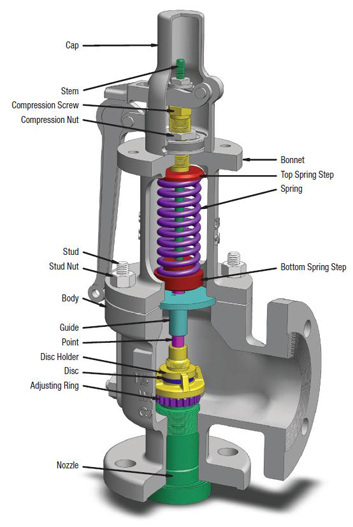
Relief Valves
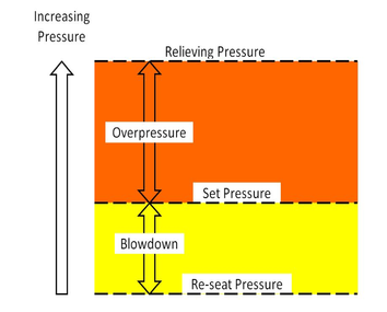
A relief valve (RV) is a type of valve used to control or limit the pressure in a system or vessel which can build up by a process upset, instrument or equipment failure, or fire. The pressure is relieved by allowing the pressurised fluid to flow from an auxiliary passage out of the system. Working: The safety valve will start to open; reach full lift and close over a range of pressures. There are three pressures that are important when specifying a relief valve. Set pressure – This is the pressure at which the safety valve will begin to open. Relieving pressure – This is the pressure at which the safety valve is fully open and working at full capacity. Re-seat pressure – The pressure at which the safety valve closes after a relieving event. Types of Relief Valves
Pressure relief valve (PRV) or pressure safety valve (PSV): The difference between PRV & PSV is that PSVs have a manual lever to activate the valve in case of emergency, while most PRVs are spring operated. At lower pressures some use a diaphragm in place of a spring. The oldest PRV designs use a weight to seal the valve. Relief valve (RV): A valve used on a liquid service, which opens proportionally as the increasing pressure overcomes the spring pressure. Safety valve (SV): Used in vapor/gas service. Most SVs are full lift or snap acting, in that they pop completely open. Safety relief valve (SRV): A relief valve that can be used for gas or liquid service. However, the set pressure will usually only be accurate for one type of fluid at a time. |
|
Low-pressure safety valve (LPSV): An automatic system that relieves by the static pressure of a gas. The relieving pressure is small and near the atmospheric pressure.
Vacuum pressure safety valve (VPSV): An automatic system that relieves by the static pressure of a gas. The relieving pressure is small, negative and near the atmospheric pressure.
Low and vacuum pressure safety valve (LVPSV): An automatic system that relieves by the static pressure of a gas. The relieving pressure is small, negative or positive, and near the atmospheric pressure.
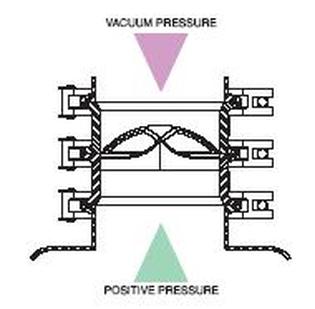
Pressure vacuum release valve (PVRV): A combination of vacuum & pressure relief valve in one housing. Used on storage tanks for liquids to prevent implosion or over pressure.
Modulating valve: Opens in proportion to the overpressure.
Snap acting valve: The opposite of modulating, refers to a valve that "pops" open. It snaps into full lift in milliseconds. Usually accomplished with a skirt on the disc so that the fluid passing the seat suddenly affects a larger area and creates more lifting force.
Pilot-operated relief valve (POSRV, PORV, POPRV): A device that relieves by remote command from a pilot valve which is connected to the upstream system pressure.
Temperature and Pressure Safety Relief Valve: This device is typically used on potable water heaters. In addition to its pressure-relief function, it also includes a temperature-sensing element which causes the device to open at a predetermined temperature regardless of pressure. The set temperature on these devices is usually 210°F.
Vacuum pressure safety valve (VPSV): An automatic system that relieves by the static pressure of a gas. The relieving pressure is small, negative and near the atmospheric pressure.
Low and vacuum pressure safety valve (LVPSV): An automatic system that relieves by the static pressure of a gas. The relieving pressure is small, negative or positive, and near the atmospheric pressure.
Pressure vacuum release valve (PVRV): A combination of vacuum & pressure relief valve in one housing. Used on storage tanks for liquids to prevent implosion or over pressure.
Modulating valve: Opens in proportion to the overpressure.
Snap acting valve: The opposite of modulating, refers to a valve that "pops" open. It snaps into full lift in milliseconds. Usually accomplished with a skirt on the disc so that the fluid passing the seat suddenly affects a larger area and creates more lifting force.
Pilot-operated relief valve (POSRV, PORV, POPRV): A device that relieves by remote command from a pilot valve which is connected to the upstream system pressure.
Temperature and Pressure Safety Relief Valve: This device is typically used on potable water heaters. In addition to its pressure-relief function, it also includes a temperature-sensing element which causes the device to open at a predetermined temperature regardless of pressure. The set temperature on these devices is usually 210°F.
|
Rupture Disc
A rupture disc (also known as a burst disc, bursting disc, or burst diaphragm) is a non-reclosing pressure relief device that, in most uses, protects a pressure vessel, equipment or system from over-pressurization or potentially damaging vacuum conditions. *Citation Needed* |
|
Safety Integrity Level
|
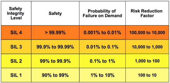
Safety Integrity Level (SIL) is defined as a relative level of risk-reduction provided by a safety function, or to specify a target level of risk reduction.
In simple terms, SIL is a measurement of performance required for a Safety Instrumented Function (SIF). In the European Functional Safety standards based on the IEC 61508 standard four SILs are defined; with SIL 4 being the most dependable and SIL 1 being the least. A SIL is determined based on a number of quantitative factors in combination with qualitative factors such as development process and safety life cycle management. |
|
SIL Classification
i. Matrix Method
ii. Risk Parameter Graph
iii. Layer of Protection Analysis (LOPA)
ii. Risk Parameter Graph
iii. Layer of Protection Analysis (LOPA)
Layer of Protection Analysis (LOPA)
|
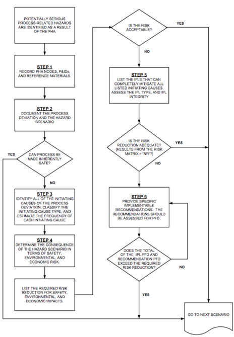
Layers of protection analysis (LOPA) is a semi-quantitative methodology that can be used to identify safeguards that meet the independent protection layer (IPL) criteria established by CCPS1 in 1993.
LOPA is not just another hazard assessment or risk assessment tool. It is an engineering tool used to ensure that process risk is successfully mitigated to an acceptable level. It can be used at any point in the lifecycle of a project or process, but it is most cost effective when implemented during front-end loading when process flow diagrams are complete and the P&IDs are under development. Application LOPA is typically applied after a qualitative hazards analysis has been completed, LOPA Process 1) Record all reference documentation, including hazards analysis documentation, pressure relief valve design and inspection reports, protection layer design documents, etc. 2) Document the process deviation and hazard scenario under consideration by the team. 3) Identify all of the initiating causes for the process deviation and determine the frequency of each initiating cause. 4) Determine the consequence of the hazard scenario. This evaluation should include an examination of safety, environmental, and economic losses. 5) List the IPLs that can completely mitigate all listed initiating causes. The IPLs must meet the independence, specificity, dependability, and auditability requirements. 6) Provide specific implementable recommendations. The recommendations from the LOPA team must be considered options for implementation. |
|
LOPA
|

LOPA Worksheet
|
Out of these,
|
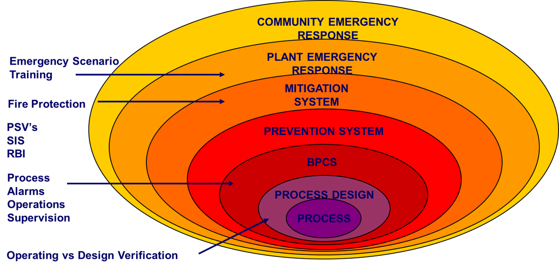
Prevention System includes the following:
|
Mitigation System includes the following:
|
Process Dynamics & Control
Module 1
Sections 1.1, 1.2, 1.3, 1.4, 1.5, and 1.6 of the first reference will be covered in full.
Among these section 1.4 will be covered later.
Module 2
Sections 2.1, 2.2, 2.3 fully, and
Sections 2.4.1, 2.4.2, 2.4.5, 2.4.6 will be covered.
Module 3
Sections 3.1, 3.3, 3.4, and 5.5 will be covered; except for the solved example 5.5
Module 4
Sections 4.1, 4.2, 4.3, and 4.4 will be covered.
Module 5
Section 6.2, excluding 6.2.1, 6.2.2, 6.2.3, and 6.2.4 will be covered.
Sections 6.4, and 6.5 will be covered fully.
Module 6
Sections 7.1, 7.2, 7.5, and 7.6.1 will be covered.
Module 7
Sections 10.1, 10.2, and 10.3 will be covered.
Module 8
Section 11.1 up to example 11.1, and sections 11.3, and 11.5.1 will be covered.
Module 9
The distillation column example will be covered here.
Module 10
Sections 13.1, 13.2, 13.3, 13.4, 13.6, and 13.7 will be covered.
For Process Dynamics and Control” by Dale E. Seborg, Thomas F. Edgar, Duncan A. Mellichamp, and Francis J. Doyle III ,3 Ed., John Wiley & Sons (Asia) Pvt. Ltd., New Delhi. Click here
